Combinatorial logic circuits
A logic circuit whose output is a logical function of it's input.
Moore's law
Moore's law, proposed in 1965, states that the number of transistors on a chip will double every 12-18 months. As a consequence the cost of computer components has decreased, physical proximity means faster operations, smaller size allows for embedded systems and computers need less power and cooling.
Boolean algebra
| Rule | Name |
|---|---|
| $(x\vee y)\vee z \equiv x \vee y\vee z)$ | associativity |
| $(x\wedge y)\wedge z \equiv x\wedge (y\wedge z)$ | associativity |
| $x \vee y \equiv y \vee x$ | commutativity |
| $x \wedge y \equiv y \wedge x$ | commutativity |
| $x \vee \text{False} \equiv x$ | identity |
| $x \wedge \text{True} \equiv x$ | identity |
| $x \vee x \equiv x$ | idempotence |
| $x \wedge x \equiv x$ | idempotence |
| $\neg (x \vee y) \equiv \neg x \wedge \neg y$ | De Morgan's law |
| $\neg(x \wedge y) \equiv \neg x \vee \neg y$ | De Morgan's law |
| $\neg (\neg x) \equiv x$ | double negation |
| $x \vee \neg x \equiv \text{True}$ | excluded middle |
| $x \wedge \neg x \equiv \text{False}$ | excluded middle |
| $x \vee (x \wedge y) \equiv x$ | absorption |
| $x \wedge (x \vee y) \equiv x$ | absorption |
| $x \wedge (y \vee z) \equiv (x \wedge y) \vee (x \wedge z)$ | distributivity |
| $x \vee (y \wedge z) \equiv (x \vee y) \wedge (x \vee z)$ | distributivity |
| $x \vee \text{True} = \text{True}$ | annihilation |
| $x \wedge \text{False} \equiv \text{False}$ | annihilation |
Karnaugh maps
Karnaugh maps can be used to simplify Boolean expressions. Consider the expression $(A \wedge B \wedge\neg C \wedge D) \vee(A \wedge\neg B \wedge\neg C \wedge D) \vee(\neg A \wedge\neg B \wedge C \wedge D) \vee(\neg A \wedge B \wedge C \wedge D)$. As a Karnaugh map, this is
| CD\AB | 00 | 01 | 11 | 10 |
|---|---|---|---|---|
| 00 | 0 | 0 | 0 | 0 |
| 01 | 0 | 0 | 1 | 1 |
| 11 | 1 | 1 | 0 | 0 |
| 10 | 0 | 0 | 0 | 0 |
From this, it is clear there are 2 groups of 2 and the expression can be simplified to $(\neg A \wedge C \wedge D) \vee(A \wedge\neg C \wedge D)$
Group size must be a power of 2. The simplest expression is obtained from the minimum number of groups. Groups can wrap around and overlap.
In the example below there are two groups, the first contains the first and last columns and the second includes the top right item and the cell adjacent to it's right. Therefore the simplified expression is $\neg B \vee(\neg A \wedge\neg C)$.
| C\AB | 00 | 01 | 11 | 10 |
|---|---|---|---|---|
| 0 | 1 | 1 | 0 | 1 |
| 1 | 1 | 0 | 0 | 1 |
If there are no possible groupings the expression can't be simplified. If there is a don't care condition then it doesn't matter if it's included in a group or not, whichever is simpler.
Adder
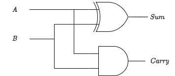
1-bit half adder
The 1-bit half adder is the most simple addition circuit. It adds two bits and outputs the sum and carry.
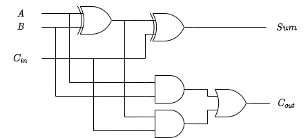
1-bit full adder
The full adder includes a carry in input.
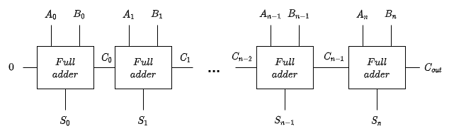
N-bit full adder
The n-bit full adder can be created by chaining 1-bit full adders.
N-bit adder/subtractor
An adder/subtractor can be created by adding a control line, $Z$. When
the line is low, the second number is added to the first and when it's
high the second number is subtracted.
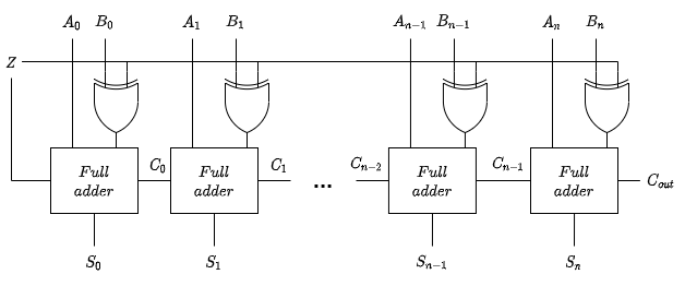
When $Z$ is high the circuit applies two's complement to the second number by inverting the bits using the XOR gates and adding 1 using the carry in. When $Z$ is low it works the same as the normal n-bit adder.
Active high and active low
Circuits can be either active high or active low. In an active high circuit a 1 is active and a 0 is inactive. In an active low circuit a 0 is active and a 1 is inactive.
Encoder and decoder
An encoder takes $n$ distinct inputs and maps them to a combination of $\log n$ outputs. The following shows an active-high 4 to 2 encoder and it's truth table.
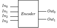
| $In_0$ | $In_1$ | $In_2$ | $In_3$ | $Out_0$ | $Out_1$ |
|---|---|---|---|---|---|
| 1 | 0 | 0 | 0 | 0 | 0 |
| 0 | 1 | 0 | 0 | 0 | 1 |
| 0 | 0 | 1 | 0 | 1 | 0 |
| 0 | 0 | 0 | 1 | 1 | 1 |
A decoder takes $n$ inputs and maps them to one of $2^n$ distinct outputs. The following shows an active-high 2 to 4 decoder and it's truth table.
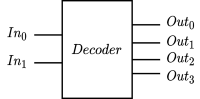
| $In_0$ | $In_1$ | $Out_0$ | $Out_1$ | $Out_2$ | $Out_3$ |
|---|---|---|---|---|---|
| 0 | 0 | 1 | 0 | 0 | 0 |
| 0 | 1 | 0 | 1 | 0 | 0 |
| 1 | 0 | 0 | 0 | 1 | 0 |
| 1 | 1 | 0 | 0 | 0 | 1 |
Encoders can be used to translate analogue signals into digital ones and decoders can be used for addressing memory locations in a processor.
Multiplexer and demultiplexer
A multiplexer (shortened to mux) takes $n$ inputs and $\log n$ switches to decide which input should be the output.
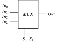
| $S_0$ | $S_1$ | $Out$ |
|---|---|---|
| 0 | 0 | $In_0$ |
| 0 | 1 | $In_1$ |
| 1 | 0 | $In_2$ |
| 1 | 1 | $In_3$ |
A demultiplexer (shortened to demux) does the opposite of a multiplexer.
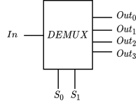
| $S_0$ | $S_1$ | $Out_0$ | $Out_1$ | $Out_2$ | $Out_3$ |
|---|---|---|---|---|---|
| 0 | 0 | $In$ | 0 | 0 | 0 |
| 0 | 1 | 0 | $In$ | 0 | 0 |
| 1 | 0 | 0 | 0 | $In$ | 0 |
| 1 | 1 | 0 | 0 | 0 | $In$ |
Multiplexers and demultiplexers can be used in communication systems. They allow multiple signals to be transmitted on a single cable, such as a telephone line. They are also used in other scenarios where inputs and outputs need to be switched between.